The Evolution of Circular Connectors: From Legacy Systems to Modern Solutions
Introduction
Circular connectors have powered electrical and data links for more than half a century. Engineers value the family for its compact geometry, rugged metal shells, and intuitive mating. The story of the circular connector mirrors the progress of industrial electronics. As systems shrink, speeds rise, and environments grow harsher, connector design evolves in parallel. This article traces that journey. We examine legacy radio plugs, the birth of the standardized M‑series, and the latest high‑speed, push‑pull, and hybrid solutions. We compare the merits of the M8 connector, the M12 connector, and the M16 connector across sensors, drives, and industrial Ethernet. Along the way we highlight reliability metrics, sealing science, and electromagnetic compatibility. We explain why modern designers still choose circular connectors and what lies ahead. We close with the unique advantages that YW brings to this dynamic field.
1. Legacy Roots: The Radio Era to the Machine Age
The earliest circular connectors date to 1930s radio equipment. Aluminum shells, bakelite inserts, and threaded couplings defined the first generation. Designers needed an interface that resisted vibration during aircraft maneuvers. Threaded barrels gave that security. Contact counts were low—often two or three pins for power and audio lines.
World War II accelerated development. Military standards such as MIL‑C‑5015 and later MIL‑DTL‑38999 introduced shell polarization, crimp contacts, and environmental seals. Engineers adopted cadmium and later zinc‑nickel plating to guard against corrosion. These connectors moved from bombers to factory floors as surplus stock found civilian use.
By the 1960s, numerical control machines demanded quick disconnect. Bayonet couplings cut mating time while keeping IP54 ingress ratings. However, size and weight still limited adoption in tightly packed control cabinets.
Birth of Metric Miniatures
German automation firms led by Hirschmann, Binder, and Phoenix Contact began miniaturizing mil‑spec ideas. They replaced inch threads with metric dimensions. The M‑coding system used the outer thread diameter as its label. M16 arrived first for sensors that needed up to 12 contacts. Soon designers wanted even smaller plugs. M12 followed with twelve‑millimeter threads, then the eight‑millimeter M8 connector. These formats now dominate industrial automation.
2. The Automation Boom and New Demands
Computerized manufacturing exploded in the 1980s. Programmable logic controllers (PLCs) spread across assembly lines. Sensors multiplied on every axis. Wiring harnesses ballooned. Field technicians required modular, keyed, and field‑installable interfaces. Circular connectors answered the call.
Factories also grew harsh. Cutting fluids, welding spatter, and constant vibration punished cables. IP67 sealing became table stakes. Polyurethane over‑molds relieved cable strain and blocked moisture wicking. Nickel‑plated brass resisted chemicals better than bare aluminum.
Data moved from parallel to serial networks. INTERBUS, DeviceNet, and Profibus demanded 1 Mbit/s over shielded twisted pairs. The M12 connector evolved new codings—A‑code for sensors, B‑code for Profibus, and later D‑code for 100 Base‑T4 Ethernet. Engineers kept the same shell geometry while re‑keying the insert to prevent cross‑mating. That compatibility protected legacy investments.
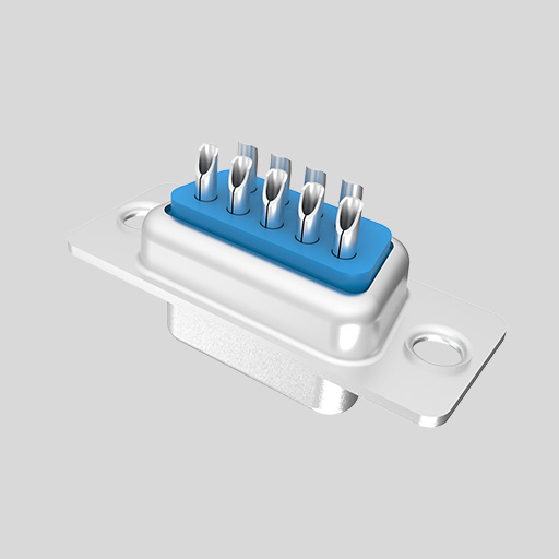
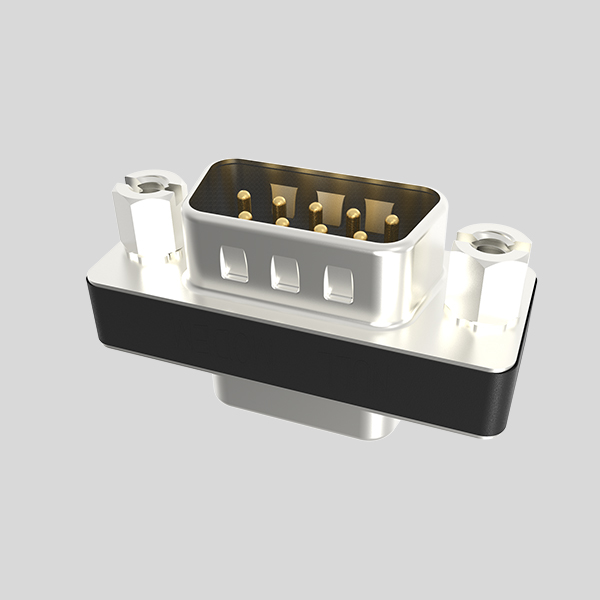
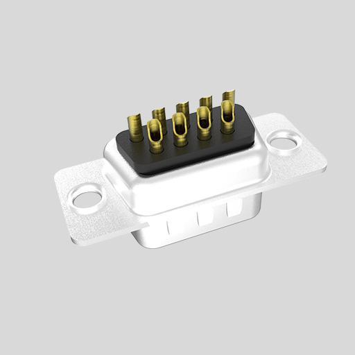
3. Anatomy of a Circular Connector
A circular connector consists of five core elements. First, the shell. In stainless steel or nickel‑plated brass it forms Faraday shielding and mechanical protection. Second, the insert. High‑temperature thermoplastics position contacts with ±0.05 mm tolerance. Third, the contacts. Copper alloys with 3–5 µm gold over 1 µm nickel ensure ≥1000 mating cycles and <10 mΩ resistance. Fourth, the coupling mechanism. Threads, bayonet lugs, or push‑pull latches secure the halves. Fifth, sealing interfaces. O‑rings and over‑molded grommets provide up to IP69K wash‑down resistance.
Engineers manage three failure modes: mechanical fatigue, galvanic corrosion, and ingress of contaminants. They specify 360° braid termination for EMC, select PUR or TPE jackets to match solvents, and design anti‑vibration lock‑nuts that survive 20 g RMS.
4. Standardization of the M‑Series
The International Electrotechnical Commission (IEC) codified circular connectors in IEC 61076‑2‑1xx. The M8 connector appears in 61076‑2‑104, the M12 connector in 61076‑2‑101, and the M16 connector in 61076‑2‑106. Each document defines contact layouts, key positions, and performance classes.
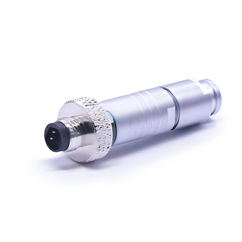
M8 Connector
The M8 connector targets miniature sensors and actuators. Typical currents run 2 A per pin with 60 V rating. Four‑pin A‑coded plugs dominate proximity switches and photo eyes. Engineers value the M8’s 7.5 mm panel hole and 8 mm wrench flat that conserves board space. Cable assemblies weigh 30 % less than M12 variants, reducing drag on delta robots.
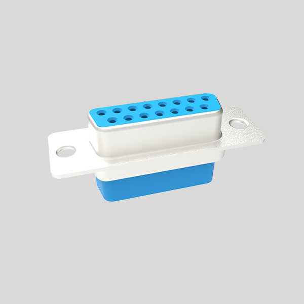
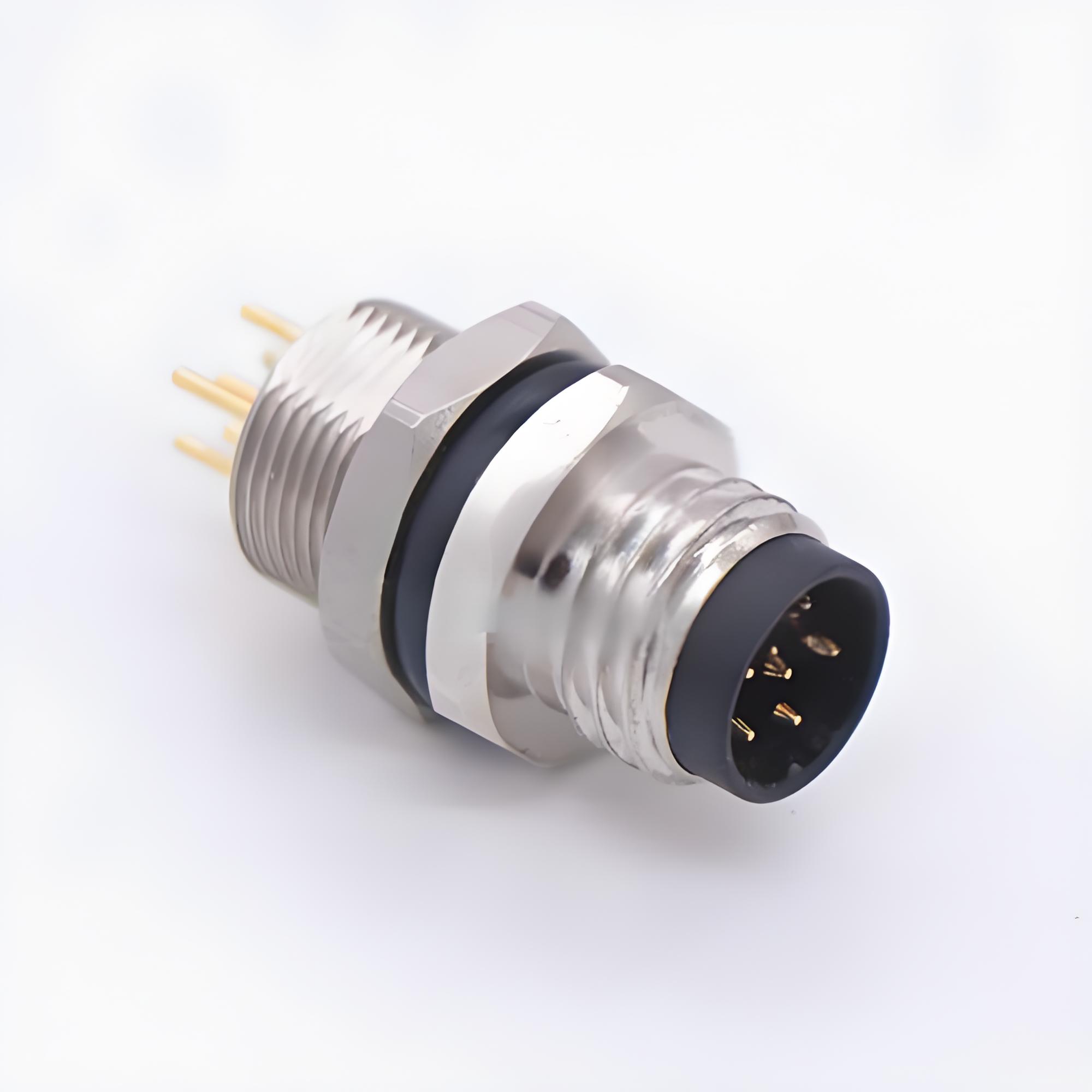
M12 Connector
The M12 connector balances size and versatility. It supports up to 10 A through K‑coded power inserts or 10 Gbit/s through X‑coded data inserts. Designers can mix power and Ethernet in a single shell by using hybrid codings like Y‑code. Field‑installable versions accept three cable OD ranges via interchangeable clamping sleeves. Technicians finish an IP67 termination in under 90 seconds without soldering.
M16 Connector
The M16 connector offers up to 19 contacts. This density serves servo feedback loops where incremental encoders need multiple signal pairs plus shield drains. Power contacts carry 7 A continuous, handling small stepper motors. Threaded couplings resist 2 Nm torque for secure retention in mobile machinery.
5. Application Deep Dives
5.1 Sensors and Actuators
Smart factories deploy thousands of proximity switches, pressure transducers, and thermal probes. Designers often choose the M8 connector here. IP67 sealing prevents coolant ingress. Chrome‑plated brass shells endure 100 h salt‑spray tests. Color‑coded knurling aids quick sensor swaps.
5.2 Industrial Ethernet
Modern PLC backbones rely on 100 Mbit/s or Gigabit Ethernet. The M12 connector with D‑ or X‑coding delivers Cat‑6A performance in oil‑soaked trenches. Engineers maintain link budgets under 3 dB thanks to symmetrical pin geometry and 360° shield mating.
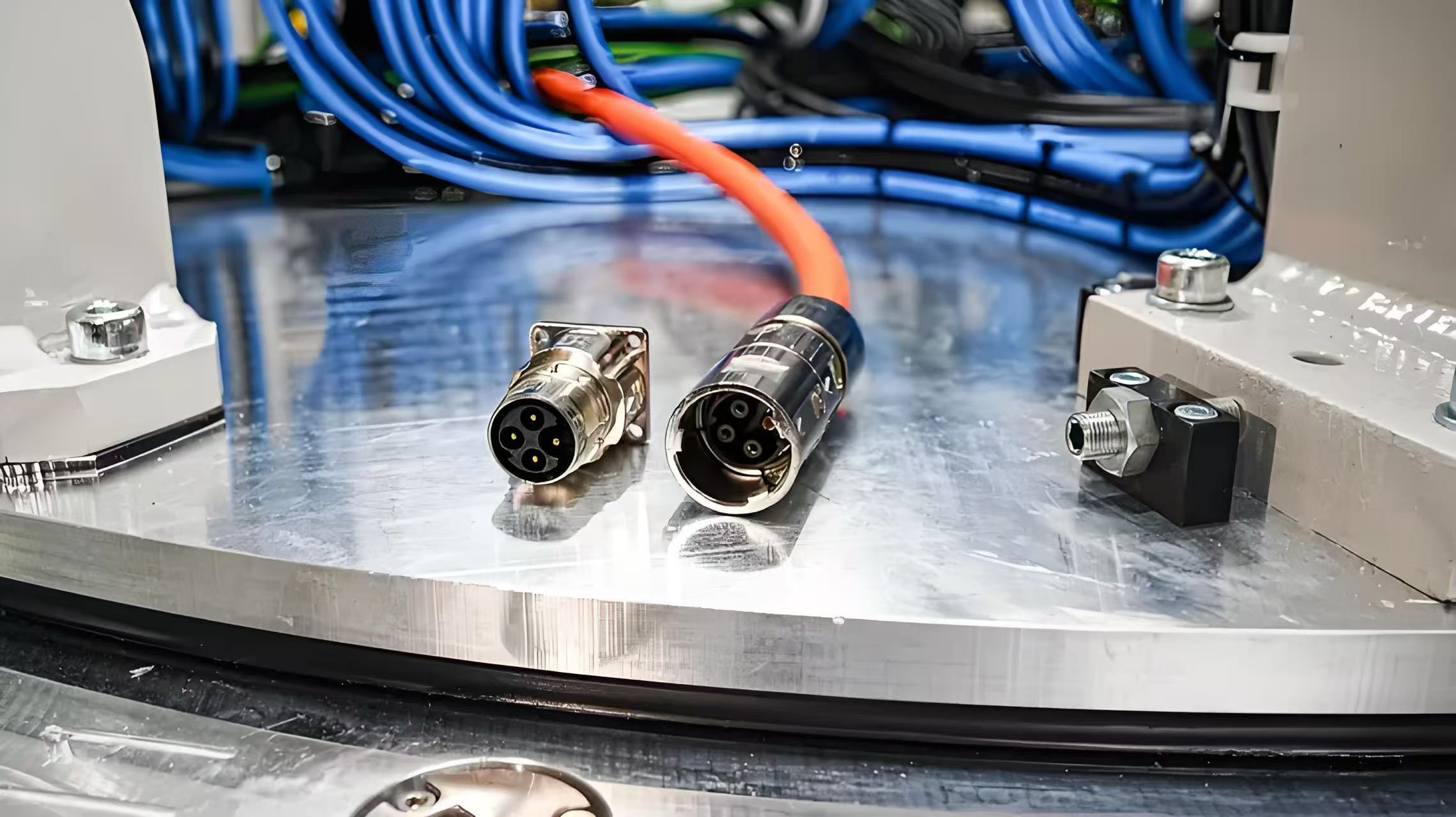
5.3 Drive Power and Feedback
Servo drives combine 60 V feedback signals with 400 V three‑phase power. The M16 connector handles this blend by using eight signal contacts plus three 16 A power contacts. Over‑molded YW assemblies integrate PUR jackets that resist hydraulic oil.
5.4 Transportation and Rail
Rolling stock faces shock, brake dust, and 1000 h UV exposure. Circular connectors excel here. M12 A‑coded plugs carry door sensors. M12 S‑coded handles 12 A for LED lighting. YW designs meet EN 45545‑2 fire‑smoke norms.
5.5 Medical Equipment
Dialysis pumps and infusion controllers require wipe‑down hygiene and high cycle counts. M8 stainless steel versions withstand autoclave steam at 134 °C for 20 min. Helix latching shaves seconds off probe swaps, speeding patient throughput.
6. Environmental and EMC Considerations
Ingress Protection (IP) ratings grade resistance to dust and water. IP67 withstands 1 m immersion for 30 min. IP69K survives 100 bar jets at 80 °C. YW uses double‑lip O‑rings and laser‑welded shells to maintain IP69K after 500 mating cycles.
Electromagnetic compatibility grows tougher in 5G factories. High‑frequency currents leak through cable braids. Engineers deploy 360° wrap‑around contacts inside circular connectors. They combine braided drains with copper‑foiled shields. Ferrite rings at the rear nut damp common‑mode noise above 100 MHz.
7. Modern Innovations
7.1 Push‑Pull Locking
Push‑pull couplings allow one‑hand mating in blind installs. A spring cage grabs the panel receptacle. Tests show technicians cut install times by 40 % versus threads. YW offers IP65 push‑pull variants that share A‑coding with threaded M12 connectors for backward fit.
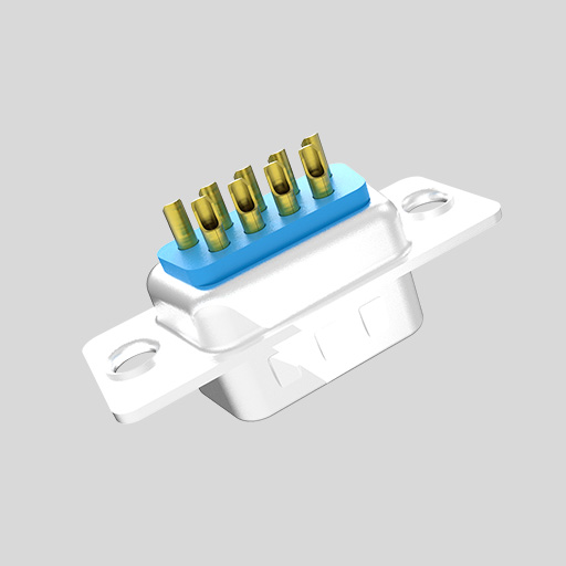
7.2 Over‑Molded Hygienic Designs
Food plants require crevice‑free surfaces. Over‑molded connectors embed tails flush with cable jackets. Smooth PUR shells eliminate bacterial traps and stand up to caustic foams. M12 hygienic versions feature blue jackets for optical detection.
7.3 Hybrid Power + Data
Robots hunger for slim cabling. YW’s Y‑coded M12 connector carries 2x 16 A plus Cat‑5e on four signal pins. Single‑cable technology lowers mass by 30 % and cuts robot settling time.
7.4 High‑Speed Data
The X‑coded M12 reaches 10 Gbit/s over 60 m. Engineers route differential pairs with 100 Ω impedance inside the insert. YW machines insert cavities within ±0.02 mm to control skew. Gold‑plated contacts show <20 ps delay mismatch.
8. Digital Transformation and IIoT
Industry 4.0 platforms rely on sensor density and deterministic Ethernet. Circular connectors remain vital because they merge ruggedness with gigabit speeds. Edge nodes in automotive paint shops record temperature, particulate, and vibration. They feed MQTT data upstream over M12 Ethernet. Wireless cannot match reliability near spray robots. Connectors guarantee power and signal delivery.
Predictive maintenance platforms depend on consistent impedance across thousands of mated pairs. YW batch‑tests every M12 assembly using time‑domain reflectometry. We publish S‑parameter files so PCB engineers can model channel loss. Such transparency speeds IIoT deployment.
9. Selecting the Right Circular Connector
Engineers weigh six factors. First, current and voltage. Second, contact count. Third, data rate. Fourth, environmental seal. Fifth, mechanical load. Sixth, assembly time. The M8 connector fits low‑current sensors in tight pockets. The M12 connector covers most control networks and mid‑power devices. The M16 connector takes dense pin maps and mixed power‑signal duties.
Field service also matters. Threaded couplings excel where technicians wear gloves. Push‑pull styles fit blind mating. Bayonet latches reduce half‑turn misalignment.
YW publishes application guides that align connector families with IEC 61131‑2 I/O classes. We provide sample kits so design teams can test real hardware early.
10. Why Engineers Choose YW
YW focuses on circular connectors. We machine shells in‑house from European brass, keeping tolerances within ±8 µm. Our automated plating line deposits nickel then white bronze to achieve 500 h salt‑spray resistance.
We over‑mold cable assemblies using low‑pressure molding to protect inner insulation. Our IP69K designs survive 200 wash cycles with 1 % leak rate.
YW holds ISO 9001, ISO 13485, and IATF 16949 certifications. We support PPAP Level 3 for automotive launches. A global logistics network ships samples in 48 hours.
Engineers trust our 24‑hour FAE hotline. We answer pin‑out, crimp tool, and EMC questions in real time. We also supply 3D CAD files and step models. This speeds enclosure design and shortens time to market.
Our YW Rapid‑Mix cell can build 10 custom over‑molded M12 connector assemblies in three days. You no longer wait eight weeks for prototypes.
The result: faster design, lower risk, and better performance.
Conclusion
Circular connectors continue to adapt. From bulky radio plugs they have become compact, high‑speed, and application‑tailored components. The M8 connector drives miniaturized sensors. The M12 connector powers Industrial Ethernet and hybrid power links. The M16 connector solves dense mixed‑signal challenges. New lock styles, hygienic shells, and 10 Gbit/s data rates keep them relevant in Industry 4.0.
YW leads this evolution with precision machining, rapid customization, and global engineering support. We help customers connect power and data with confidence.
Contact YW today.